Plastic Injection Molding Blog

MISSION STATEMENT


"WE WANT TO USE OUR YEARS OF EXPERIENCE IN PLASTIC MOLD MAKING AND PROVIDE TOTAL SOLUTION TO OUR CUSTOMERS PROBLEMS. WITH OUR NETWORKS OF GOOD MOLD MAKERS ALL AROUND ASIAN COUNTRIES WE CAN BRING THE BEST OF QUALITY, COST AND LEAD TIME"

Nature of Business

Main Business:

Dealer of plastic injection molds and injection mold related products, services and technical support.

Other services:

General trading, Training and Consultation services, NewTechnology Introduction and Technical Support, ManufacturersAgents and Distributors of and Dealers inTrading of;

General products and services such as plastic injection molding,plastic injection machine spare part, plastic injection machineaccessories, plastic injection mold making, plastic injection mold, plastic injection mold accessories, plastic injection mold spare parts,plastic injection mold maintenance services, plastic injection moldrepair and modification services, plastic injection mold hot runner systems and other plastic injection mold support systems and newtechnologies, products secondary process and related industry such as all type spray painting, UV painting, metal plating, sputtering,vapour coating, ink printing, laser printing, hot stamping sub-assembly and assembly.

Wednesday, August 4, 2010

Injection Mould Types

Image via Wikipedia


Injection Mould Types


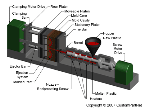
Plastic injection moulds can be categorized into two main types: cold runner mould and hot runner mould. A runner is the channel in the mold that conveys the melted plastic from the barrel of the injection molding machine to the part.


Cold Runner Mould


In a cold runner mould, the runner is cooled and ejected with the part. Every cycle, a part and a runner are produced. The obvious disadvantage of this system is the waste plastic generated. The runners are either disposed of, or reground and reprocessed with the original material. This adds a step in the manufacturing process. Also, regrind will increase variation in the injection molding process, and could decrease the plastic's mechanical properties.


Hot Runner Mould


Plastic Injection Mold - Injection CycleIn a hot runner mould, the runner is situated internally in the mould and kept a temperature above the melting point of the plastic. Runner scrap is reduced or eliminated. The major disadvantages of a hot runner are that it is much more expensive than a cold runner, it requires costly maintenance, and requires more skill to operate. Color changes with hot runner moulds can be difficult, since it is virtually impossible to remove all of the plastic from an internal runner system.

Hot runners have many advantages. They can completely eliminate runner scrap, so there are no runners to sort from the parts, and no runners to throw away or regrind and remix into the original material. Hot runners are popular in high production parts, especially with a lot of cavities.


Types of Cold Runner Moulds


There are two major types of cold runner molds: two plate and three plate.
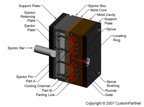
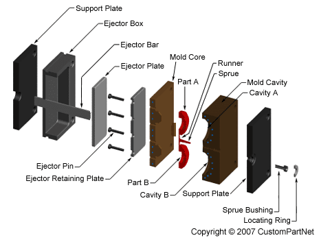
A two plate cold runner mould is the simplest type of mould. It is called a two plate mold because there is one parting plane, and the mould splits into two halves. The runner system must be located on this parting plane; thus the part can only be gated on its perimeter. A three plate mould differs from a two plate in that it has two parting planes, and the mould splits into three sections every time the part is ejected. Since the mold has two parting planes, the runner system can be located on one, and the part on the other. Three plate moulds are used because of their flexibility in gating location. A part can be gated virtually anywhere along its surface.


Types of Hot Runner Moulds


Hot runner molds are two plate moulds with a heated runner system inside one half of the mould. A hot runner system is divided into two parts: the manifold and the drops. The manifold has channels that convey the plastic on a single plane, parallel to the parting line, to a point above the cavity. The drops, situated perpendicular to the manifold, convey the plastic from the manifold to the part.
There are many variations of hot runner systems. Generally, hot runner systems are designated by how the plastic is heated. There are internally and externally heated drops and manifolds.

Externally heated hot runner channels have the lowest pressure drop of any runner system (because there is no heater obstructing flow and all the plastic is molten), and they are better for color changes none of the plastic in the runner system freezes. There are no places for material to hang up and degrade, so externally heated systems are good for thermally sensitive materials.
Internally heated runner systems require higher moulding pressures, and color changes are very difficult. There are many places for material to hang up and degrade, so thermally sensitive materials should not be used. Internally heated drops offer better gate tip control. Internally heated systems also better separate runner heat from the mould because an insulating frozen layer is formed against the steel wall on the inside of the flow channels.

A special type of hot runner system is an insulated runner. An insulated runner is not heated; the runner channels are extremely thick and stay molten during constant cycling. This system is very inexpensive, and offers the flexible gating advantages of other hot runners and the elimination of gates without the added cost of the manifold and drops of a heated hot runner system. Color changes are very easy. Unfortunately, these runner systems offer no control, and only commodity plastics like PP and PE can be used. If the mold stops cycling for some reason, the runner system will freeze and the mould has to be split to remove it. Insulated runners are usually used to make low tolerance parts like cups.


To the top of Injection Mould Types


Enhanced by Zemanta

Mold Design

The mold consists of two primary components, the injection mold (A plate) and the ejector mold (B plate). Plastic resin enters the mold through a sprue in the injection mold, the sprue bushing is to seal tightly against the nozzle of the injection barrel of the molding machine and to allow molten plastic to flow from the barrel into the mold, also known as the cavity. The sprue bushing directs the molten plastic to the cavity images through channels that are machined into the faces of the A and B plates. These channels allow plastic to run along them, so they are referred to as runners. The molten plastic flows through the runner and enters one or more specialized gates and into the cavity geometry to form the desired part.

The amount of resin required to fill the sprue, runner and cavities of a mold is a shot. Trapped air in the mold can escape through air vents that are ground into the parting line of the mold. If the trapped air is not allowed to escape, it is compressed by the pressure of the incoming material and is squeezed into the corners of the cavity, where it prevents filling and causes other defects as well. The air can become so compressed that it ignites and burns the surrounding plastic material. To allow for removal of the molded part from the mold, the mold features must not overhang one another in the direction that the mold opens, unless parts of the mold are designed to move from between such overhangs when the mold opens (utilizing components called Lifters).
Sides of the part that appear parallel with the direction of draw (The axis of the cored position (hole) or insert is parallel to the up and down movement of the mold as it opens and closes)are typically angled slightly with (draft) to ease release of the part from the mold. Insufficient draft can cause deformation or damage. The draft required for mold release is primarily dependent on the depth of the cavity: the deeper the cavity, the more draft necessary. Shrinkage must also be taken into account when determining the draft required. If the skin is too thin, then the molded part will tend to shrink onto the cores that form them while cooling, and cling to those cores or part may warp, twist, blister or crack when the cavity is pulled away. The mold is usually designed so that the molded part reliably remains on the ejector (B) side of the mold when it opens, and draws the runner and the sprue out of the (A) side along with the parts. The part then falls freely when ejected from the (B) side. Tunnel gates, also known as submarine or mold gate, is located below the parting line or mold surface. The opening is machined into the surface of the mold on the parting line. The molded part is cut (by the mold) from the runner system on ejection from the mold.Ejector pins, also known as knockout pin, is a circular pin placed in either half of the mold (usually the ejector half), which pushes the finished molded product, or runner system out of a mold.

The standard method of cooling is passing a coolant (usually water) through a series of holes drilled through the mold plates and connected by hoses to form a continuous pathway. The coolant absorbs heat from the mold (which has absorbed heat from the hot plastic) and keeps the mold at a proper temperature to solidify the plastic at the most efficient rate.

To ease maintenance and venting, cavities and cores are divided into pieces, called inserts, and sub-assemblies, also called inserts, blocks, or chase blocks. By substituting interchangeable inserts, one mold may make several variations of the same part.
More complex parts are formed using more complex molds. These may have sections called slides, that move into a cavity perpendicular to the draw direction, to form overhanging part features. When the mold is opened, the slides are pulled away from the plastic part by using stationary “angle pins” on the stationary mold half. These pins enter a slot in the slides and cause the slides to move backward when the moving half of the mold opens. The part is then ejected and the mold closes. The closing action of the mold causes the slides to move forward along the angle pins.

Some molds allow previously molded parts to be reinserted to allow a new plastic layer to form around the first part. This is often referred to as overmolding. This system can allow for production of one-piece tires and wheels.
2-shot or multi-shot molds are designed to "overmold" within a single molding cycle and must be processed on specialized injection molding machines with two or more injection units. This process is actually an injection molding process performed twice. In the first step, the base color material is molded into a basic shape. Then the second material is injection-molded into the remaining open spaces. That space is then filled during the second injection step with a material of a different color.

A mold can produce several copies of the same parts in a single "shot". The number of "impressions" in the mold of that part is often incorrectly referred to as cavitation. A tool with one impression will often be called a single impression(cavity) mold. A mold with 2 or more cavities of the same parts will likely be referred to as multiple impression (cavity) mold. Some extremely high production volume molds (like those for bottle caps) can have over 128 cavities.

In some cases multiple cavity tooling will mold a series of different parts in the same tool. Some toolmakers call these molds family molds as all the parts are related.


Mold or Die

Mold or die are the common terms used to describe the tooling used to produce plastic parts in molding.
Since molds have been expensive to manufacture, they were usually only used in mass production where thousands of parts were being produced. Typical molds are constructed from hardened steel, pre-hardened steel, aluminum, and/or beryllium-copper alloy. The choice of material to build a mold from is primarily one of economics; in general, steel molds cost more to construct, but their longer lifespan will offset the higher initial cost over a higher number of parts made before wearing out. Pre-hardened steel molds are less wear-resistant and are used for lower volume requirements or larger components. The typical steel hardness is 38-45 on the Rockwell-C scale. Hardened steel molds are heat treated after machining. These are by far the superior in terms of wear resistance and lifespan. Typical hardness ranges between 50 and 60 Rockwell-C (HRC). Aluminum molds can cost substantially less, and, when designed and machined with modern computerized equipment, can be economical for molding tens or even hundreds of thousands of parts. Beryllium copper is used in areas of the mold that require fast heat removal or areas that see the most shear heat generated.[12] The molds can be manufactured either by CNC machining or by using Electrical Discharge Machining processes


Injection Molding Machine

Mold Closed View

Mold Exploded View

Clamping Force Calculator

Cooling Time Calculator